Basic 12 Volt Boat Wiring Diagram with Battery Switch and Fuse Panel
Build a safe 12V boat wiring diagram with the right battery switch, fuse panel, tinned marine cable, and ABYC-aware component placement. Includes diagram layout and parts guidance.
A basic 12 volt boat wiring diagram needs five core elements: a battery bank with starting and house batteries, a battery switch (1-BOTH-2-OFF), a main fuse panel, properly sized marine-grade tinned copper wiring, and an ABYC-compliant grounding system. Every connection must be waterproof and vibration-resistant.
What this guide covers: How to design a reliable 12V boat wiring diagram from battery to load, marine-specific requirements that differ from RV wiring (corrosion, stray current, waterproofing), proper battery switch configurations, and the components that keep marine electrical systems safe.
What Makes Marine Wiring Different
Before diving into diagram design, understand why marine electrical systems need special attention:
Corrosion is relentless - Salt air and spray attack every connection. Marine-grade components and proper sealing aren't optional.
Vibration loosens connections - Boats shake constantly. Ring terminals, proper strain relief, and locking hardware are essential.
Water finds every gap - Moisture causes shorts, corrosion, and fires. Waterproof connections and proper routing matter.
Stray current destroys metal - Improper grounding causes galvanic corrosion that eats through hulls and hardware.
Basic 12 Volt Boat Wiring Diagram Components
A reliable boat electrical system needs these core components:
Battery Bank
- Starting battery: Dedicated to engine starting, kept isolated
- House battery: Powers accessories, lights, electronics
- Battery type: AGM or LiFePO4 (never flooded lead-acid in enclosed spaces due to hydrogen gas)
Battery Switch Configuration
The battery switch is the heart of marine electrical safety:
Single battery switch: Simple ON/OFF - rarely used on modern boats
Dual battery switch: 1-BOTH-2-OFF positions
- Position 1: Starting battery only
- Position 2: House battery only
- BOTH: Batteries paralleled (emergency only)
- OFF: All batteries isolated
Automatic Charging Relay (ACR): Modern alternative that automatically combines batteries for charging while keeping them isolated for use.
Charging Sources
- Alternator: Primary charging while motoring
- Shore power charger: When docked
- Solar panels: Keeps batteries topped off at the mooring
Distribution Panel
Marine distribution panels include:
- Main breaker: Master disconnect for the panel
- Individual breakers: One per circuit
- LED indicators: Show which circuits are active
- Waterproof construction: For wet environments
Designing Your Boat Wiring Diagram
Here's the step-by-step process for creating a basic 12 volt boat wiring diagram:
Step 1: List All Electrical Loads
Navigation and safety:
- Navigation lights (10-25W total)
- Anchor light (10-15W)
- VHF radio (1W standby, 25W transmit)
- GPS/chartplotter (10-30W)
- Depth sounder (5-15W)
- Bilge pump (15-30W per pump)
- Horn (5-10W)
Convenience loads:
- Cabin lights (2-10W each)
- 12V outlets (for charging devices)
- Freshwater pump (30-60W)
- Stereo (20-100W)
- Refrigeration (30-60W)
Engine-related:
- Engine instruments (5-15W)
- Trim tabs (motor draws 10-15A during adjustment)
- Electric fuel pump if equipped
Step 2: Calculate Wire Sizes
Marine wiring has stricter requirements than automotive or RV applications:
ABYC standards require:
- 3% maximum voltage drop for critical circuits (navigation, bilge pumps)
- 10% maximum for non-critical circuits
Wire sizing formula: Length (feet) x Current (amps) x 10.75 / Allowable voltage drop = Circular mils needed
Use marine-grade tinned copper wire -- it resists corrosion far better than bare copper. Our fuse and wire gauge calculator handles the math for you, including voltage drop and fuse sizing for any cable length and current.
Step 3: Plan Circuit Protection
Every positive wire needs fuse or breaker protection at its power source:
| Circuit | Typical Wire | Fuse/Breaker |
|---|---|---|
| Navigation lights | 14 AWG | 10A |
| Anchor light | 16 AWG | 5A |
| VHF radio | 14 AWG | 10A |
| Bilge pump | 14 AWG | 15A |
| Cabin lights | 16 AWG | 10A |
| 12V outlets | 14 AWG | 15A |
| Water pump | 14 AWG | 15A |
Critical safety rule: Bilge pumps should be wired directly to the battery with an inline fuse, bypassing the main switch. This ensures they work even when the boat is unattended.
Step 4: Design the Ground System
Marine grounding is crucial for both safety and corrosion prevention:
DC negative system:
- All negative wires return to a common bus bar
- Bus bar connects to battery negative with heavy gauge wire
- Keep DC ground isolated from engine block (unless bonded per ABYC standards)
Bonding system:
- Connects all underwater metals
- Prevents galvanic corrosion between dissimilar metals
- Requires proper sizing and zinc anodes
AC grounding (if equipped):
- Completely separate from DC ground
- Requires galvanic isolator when connected to shore power
Marine-Specific Wiring Requirements
Wire and Cable Specifications
Use only marine-grade wire:
- Tinned copper strands (not bare copper)
- Oil and fuel resistant insulation
- Rated for temperature extremes
- UL Marine listed or ABYC compliant
Connection requirements:
- Adhesive-lined heat shrink on all connections
- Ring terminals preferred over spade terminals
- Crimp connections must use proper marine crimpers
- No electrical tape - it traps moisture
Routing and Protection
- Keep wiring above bilge water level
- Use split loom or conduit for protection
- Avoid routing near exhaust or moving parts
- Support wires every 18 inches minimum
- Allow drip loops before connections
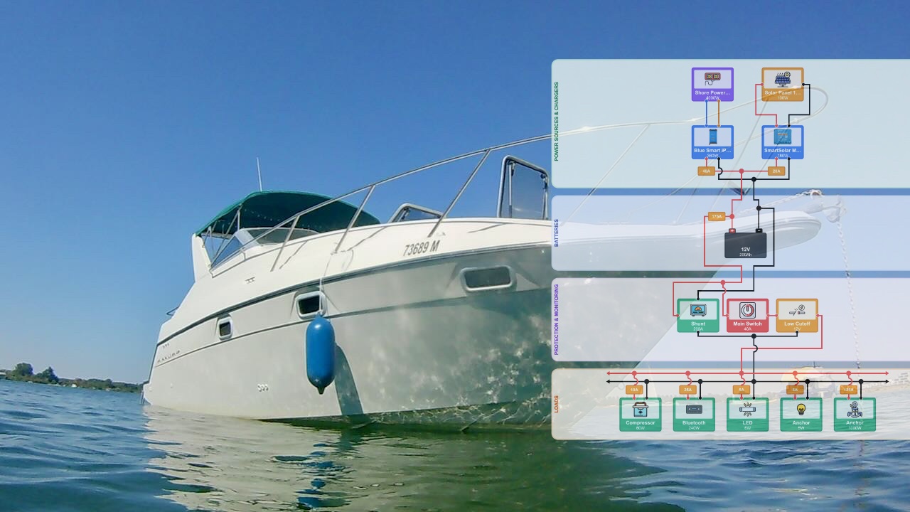
Sample Basic 12 Volt Boat Wiring Diagram
Here's a typical small boat configuration showing the key components and connections:
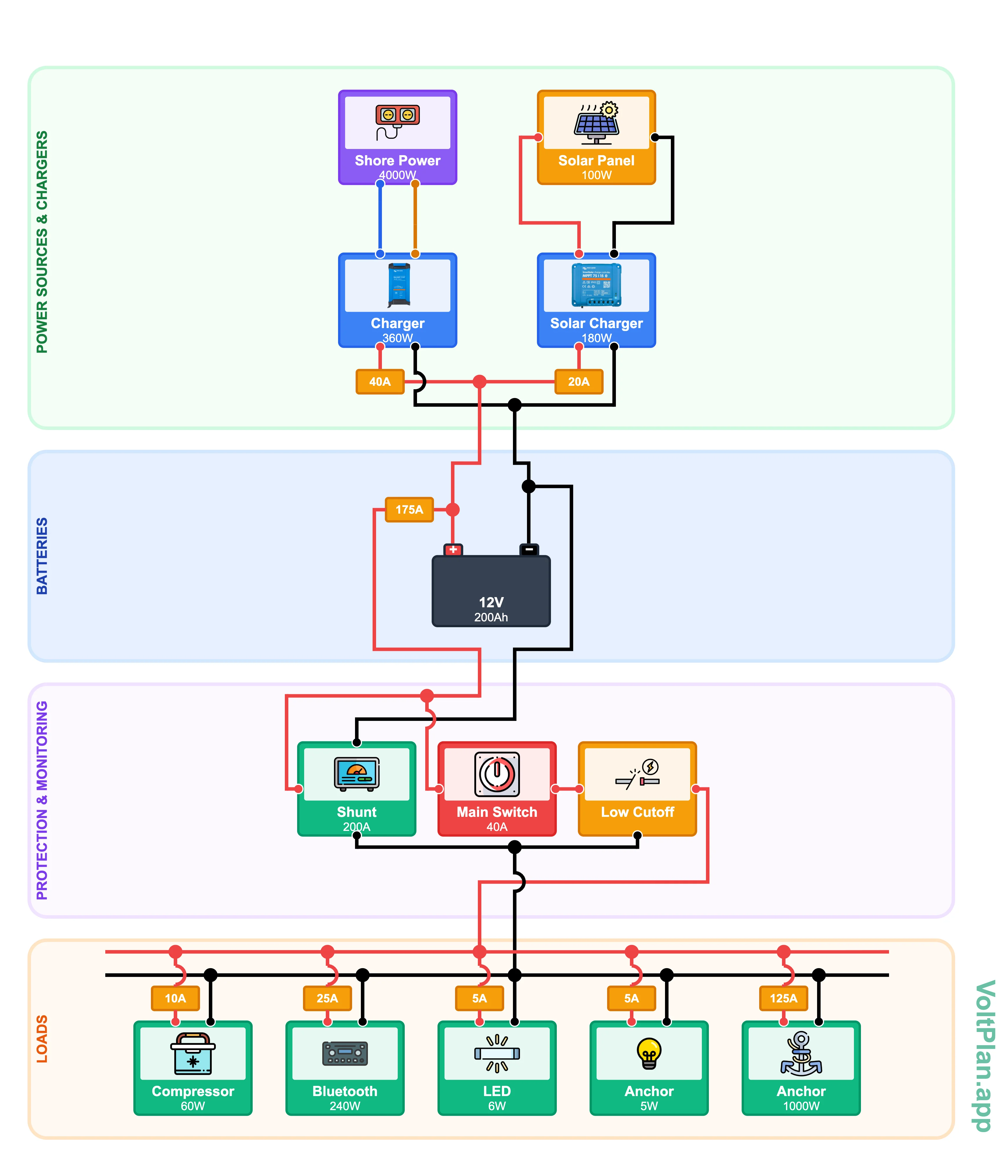
This diagram shows the essential elements: starting and house batteries with proper isolation, distribution panel with individual circuit breakers, and the critical bilge pump bypass that keeps it operational even when the main switch is off.
Using VoltPlan for Marine Wiring Diagrams
VoltPlan includes marine-specific features for boat electrical design:
- Marine templates - Start with proven boat configurations
- Component library - Battery switches, ACRs, marine panels
- Wire sizing calculator - Accounts for marine voltage drop requirements
- Professional diagram export - Document your installation
Whether you're wiring a simple day sailer or a complex cruising boat, having a proper diagram makes installation easier and troubleshooting possible.
Common Marine Wiring Mistakes
Using automotive wire - It corrodes rapidly in marine environments
Undersized battery cables - Causes voltage drop and hard starting
Skipping the galvanic isolator - Leads to severe corrosion when connected to shore power
Improper bilge pump wiring - Must bypass main switch for automatic operation
Poor connection sealing - Every connection needs heat shrink or waterproof termination
No diagram documentation - Future maintenance becomes guesswork
Next Steps
Ready to design your boat's electrical system?
- List all your electrical loads and their power requirements
- Decide on battery configuration (separate starting/house recommended)
- Plan your charging sources (alternator + shore + solar)
- Open VoltPlan and start with our marine electrical template
A well-designed marine electrical system is reliable, safe, and trouble-free. Take the time to plan it properly, use quality marine-grade components, and document everything in a clear wiring diagram.
Your boat's electrical system is too important to improvise. Plan it right from the start.
Ready to Design Your Electrical System?
Use VoltPlan's free electrical system designer to turn these concepts into reality.
Start Your Project