


Wire Gauge Chart for 12V Systems (2026): 14 AWG = 15A, 10 AWG = 35A, 4 AWG = 85A
Complete AWG to mm² reference table with ampacity for 18 AWG to 2/0 AWG — plus voltage-drop sizing steps, fuse pairing, and a full FAQ. Free calculator for any circuit.
Quick reference: 18 AWG = 7A, 16 AWG = 10A, 14 AWG = 15A, 12 AWG = 25A, 10 AWG = 35A, 8 AWG = 50A, 6 AWG = 65A, 4 AWG = 85A, 2 AWG = 110A, 1/0 AWG = 135A. These are continuous-current limits for copper cable in a bundled 12V installation. The full table, mm² equivalents, typical uses, and the step-by-step method for your specific run are below.
Wire Gauge Quick Reference
Pick the row that covers your load. The mm² column is the metric cable you buy in European shops; the ampacity is the continuous ceiling for bundled chassis wiring. For fuse sizing, see the 12V fuse size chart.
| Wire Gauge | mm² (metric) | Max Amps | Typical 12V Use |
|---|---|---|---|
| 18 AWG | 0.75 mm² | 7 A | Sensor feeds, indicator LEDs, relay coils |
| 16 AWG | 1.0 mm² | 10 A | LED lighting branches, USB outlets |
| 14 AWG | 1.5 mm² | 15 A | Branch circuits, fans, switch feeds |
| — | 2.5 mm² | 20 A | Heavier lighting, vent fans (metric-only size) |
| 12 AWG | 4.0 mm² | 25 A | Water pumps, accessory sockets |
| 10 AWG | 6.0 mm² | 35 A | Compressor fridge, MPPT to battery (≤30A) |
| 8 AWG | 10.0 mm² | 50 A | DC-DC chargers, distribution feeds |
| 6 AWG | 16.0 mm² | 65 A | High-output MPPT, sub-panel runs |
| 4 AWG | 25.0 mm² | 85 A | 1000W inverters, battery to panel |
| 2 AWG | 35.0 mm² | 110 A | 1500W inverters, battery interconnects |
| 1/0 AWG | 50.0 mm² | 135 A | 2000–3000W inverters |
| 2/0 AWG | 70.0 mm² | 170 A | Large battery banks, main busbars |
Values from the VoltPlan wire gauge calculator (IEC metric cable standards at 20°C, bundled wiring). For free-air or high-temperature runs, derate by 10–20%.
To size wire for a 12V circuit, you need three numbers: the current in amps, the round-trip cable length in meters, and your maximum acceptable voltage drop (3% for most circuits, 1% for sensitive electronics). Plug these into the formula: cross-section (mm²) = (2 × length × current × 0.0175) / max voltage drop.
The key rule: Always calculate amps, round-trip distance, and acceptable voltage drop first, then choose the smallest gauge that meets those targets in both AWG and mm² so every fuse, breaker, and terminal in your build agrees.
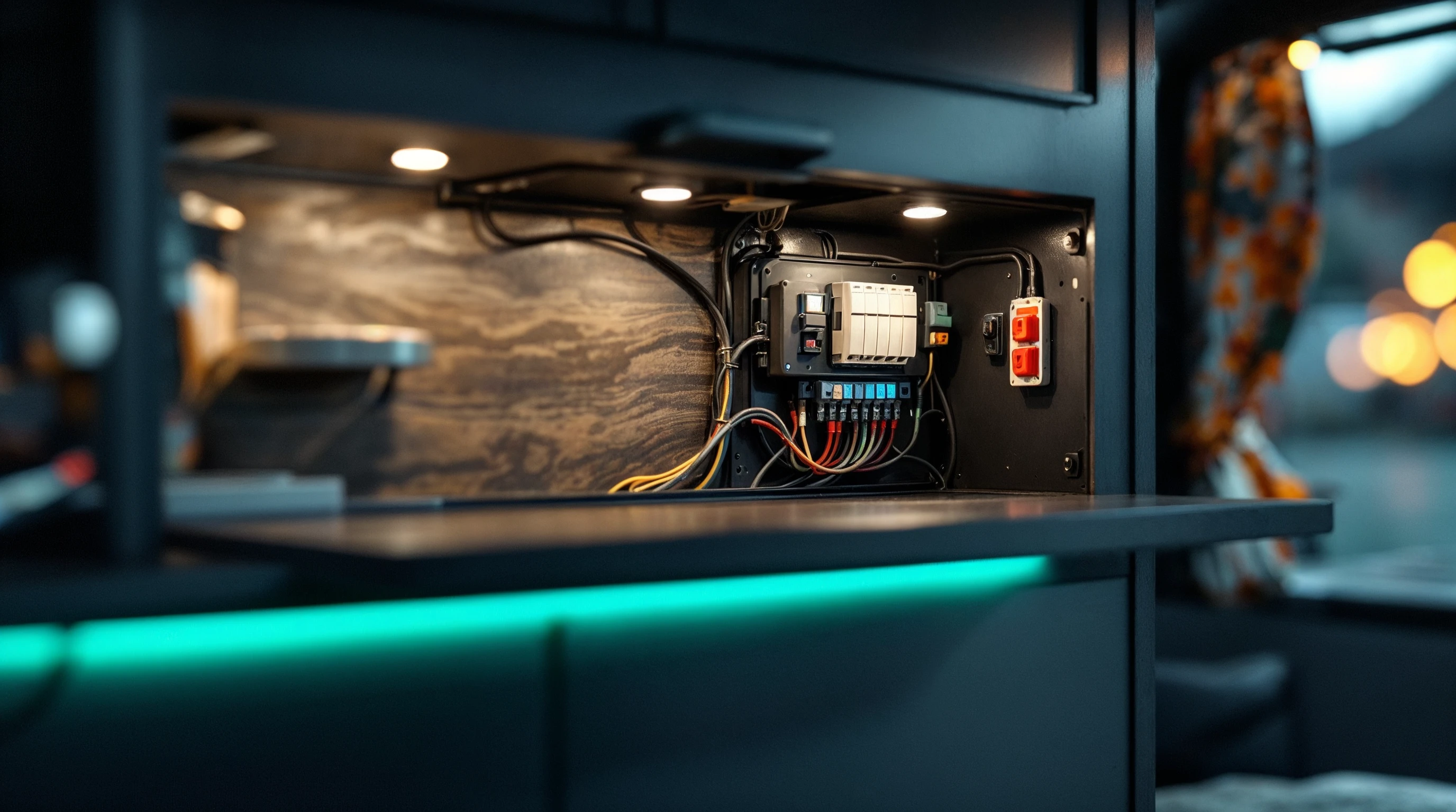 A clean electrical cabinet reminds you what you’re aiming for before cutting copper.
Why Hobbyists Need a Repeatable Method
Camper and boat projects rarely follow the neat diagrams you see in catalogs. You snake wires behind cabinets, stretch them under floorboards, and splice in upgrades months later. That means:
- Voltage drop matters more than perfect laboratory specs. Even a 0.5V loss can shut down a LiFePO4 inverter or dim LED strips.
- Components often mix standards. The solar controller spec sheet lists terminals in mm², your wire spool is in AWG, and European combiner blocks only accept ferrules sized in square millimeters.
- Safety agencies keep updating their guidance for small craft. Instead of memorizing a different rule each year, you need a quick process that works for every circuit.
If you can multiply, divide, and measure distance with a tape, you can size wire like a pro, no electrical engineering degree required.
Step 1: Capture the Real Load
Start by listing every device on the circuit. Grab manuals, look at stickers, or use a clamp meter if the equipment already runs.
- Continuous current: Anything that runs longer than 10 minutes stays at its printed amp draw. Multiply by 1.0.
- Intermittent current: Motors, pumps, and compressors spike when they start. Multiply by 1.25 to build in breathing room.
- Future headroom: If you know a second fridge or fan is coming, add its amps now. Wire is cheaper than tearing cabinets apart later.
Example: A DC fridge at 5.0A continuous and a pair of LED strip zones at 1.5A each → 5.0 + 1.5 + 1.5 = 8.0A load. Add a 25% surge factor if the fridge compressor is grumpy on hot days → 8.0 × 1.25 = 10A target current.
For more context on estimating appliance loads, revisit 12V Electrical System Basics where we break down common draws in campers.
Step 2: Measure the Run Length
Voltage drop is based on the round-trip distance (out and back). Pull a string along the exact path you plan to route the wire, measure it in feet or meters, then double it.
- Vertical detours, drip loops, and service slack count.
- For DC harnesses bundled together, use the longest conductor in the bundle as your reference.
- Write both measurements: feet for AWG charts, meters for mm² conversions.
Example: Battery to inverter path snakes 5 ft up the cabinet, 3 ft forward, and 4 ft down to the inverter. Total one-way = 12 ft. Round trip = 24 ft (7.3 m).
Step 3: Set Your Voltage-Drop Budget
Hobbyist builds work best with simple rules:
- Critical loads (inverters, DC-DC chargers, alternator feeds): ≤3% drop.
- General circuits (lights, USB, fans): ≤10% drop.
- Electronics sensitive to brownout: Stay closer to 2-3% so they never false-trip.
On a 12.8V LiFePO4 system, 3% equals roughly 0.38V. That tiny number keeps chargers from shutting off early when they expect at least 12.4V under load.
Need more detail? Our Fuse Sizing and Placement guide explains how drop targets tie directly into fuse choices and heat.
Step 4: Do the Math (It’s Easier Than It Looks)
Use the classic voltage-drop formula for copper wire:
Wire area (circular mils) = (K × I × L) / Vd
K = 10.75(resistivity constant for copper at ~20°C)I = amps from Step 1L = round-trip length in feetVd = allowed voltage drop in volts
Example Calculation
- Current
I = 50A - Round trip
L = 24 ft - Voltage drop
Vd = 0.384V
Wire area = (10.75 × 50 × 24) / 0.384 ≈ 33,656 circular mils
Look up the next-largest wire that meets or exceeds that area: 2 AWG (33.6 mm²). Never round down—always step up.
Quick Reference Table
| AWG | mm² | Circular mils | Typical continuous amps* |
|---|---|---|---|
| 14 | 2.08 | 4,107 | 15A (3% drop @15 ft) |
| 12 | 3.31 | 6,530 | 20A |
| 10 | 5.26 | 10,380 | 30A |
| 8 | 8.37 | 16,510 | 45A |
| 6 | 13.3 | 26,250 | 65A |
| 4 | 21.1 | 41,740 | 95A |
| 2 | 33.6 | 66,360 | 130A |
| 1/0 | 53.5 | 105,600 | 170A |
| 2/0 | 67.4 | 133,100 | 195A |
Based on ≤3% drop at ~15 ft round trip in a 12V system. Longer runs or higher loads require upsizing. The mm² values here are precise IEC cross-sections (what the formula requires). Standard metric cable sells the nearest stocked size: 14 AWG → 1.5mm², 12 AWG → 4mm², 10 AWG → 6mm², 4 AWG → 25mm². See the quick reference table at the top for the sizes you actually buy.
Want to skip the manual math? Use our interactive wire gauge calculator to get the exact wire size, voltage drop, and fuse recommendation for your specific setup.
Conversion Hacks
- Multiply mm² by 1,973.5 to get circular mils.
- Multiply AWG circular mils by 0.0005067 to get mm².
- Memorize three anchors: 6 mm² ≈ 10 AWG, 16 mm² ≈ 6 AWG, 35 mm² ≈ 2 AWG.
Step 5: Validate Against Protection Devices
Wire isn’t sized in isolation. After you pick a gauge, confirm:
- Fuse/breaker rating is below the wire’s ampacity but above the expected load. Example: 2 AWG typically pairs with 125A ANL fuses for inverters.
- Terminal blocks or busbars accept the conductor size. European DIN blocks might top out at 25 mm² even though the wire math points to 35 mm².
- Crimp tools and lugs match the chosen gauge. Mixing AWG lugs on mm² cable leads to loose crimps and heat.
Step 6: Document Both Units in VoltPlan
Inside VoltPlan, label each conductor with AWG / mm² / amps / length. Example: 2 AWG (33.6 mm²) • 50A • 24 ft RT • 3% drop. That note travels with your BOM, so whoever helps you later sees the reasoning immediately.
Real-World Scenarios
Solar Array Combiner
- 3 × 200W panels wired in series → ~9A @ 60V.
- Roof to charge controller = 18 ft one way (36 ft round trip).
- Voltage drop target: 2% (because MPPT controllers love stable voltage).
- Result: 12 AWG (3.31 mm²) barely makes it; bump to 10 AWG (5.26 mm²) for cooler roofs.
Dual DC-DC Chargers
- Two 60A chargers mounted near the alternator feeding the house bank 8 ft away.
- Combined load = 120A, round trip ≈ 16 ft.
- Drop target: 3% → 0.384V.
- Formula outputs ≈ 44,900 circular mils → 4 AWG (21.1 mm²). If you plan to add a third charger, jump directly to 1/0.
Galley Circuits
- Water pump 7A intermittent + LED lighting 3A continuous.
- One-way run = 10 ft, drop target = 10% (0.128V).
- Required area ≈ 5,879 circular mils → 12 AWG (3.31 mm²). That also gives headroom for a future UV sterilizer.
Common Mistakes (and How to Dodge Them)
- Using automotive charts: Many car-audio tables assume short runs and airflow under a hood. Camper walls don’t provide that cooling.
- Ignoring return path: People measure only the positive leg. Always double the distance for DC circuits.
- Mixing copper-clad aluminum (CCA): Cheap spools claim to be AWG but have higher resistance. Stick to pure copper marine-grade wire.
- Skipping ferrules: When you insert stranded mm² cable into screw terminals, ferrules prevent "cold flow" and loose connections.
- Relying on "bigger is better": Oversize wire without updating fuses and you lose the protective weak link.
Tools & Resources for Hobbyists
- VoltPlan Wire Calculator: Enter amps, length, and drop target. It outputs AWG, mm², and recommended fuse size.
- Clamp meter: Measure actual draw once the circuit runs. Klein and UNI-T make reliable hobby-level meters.
- Measuring tape or fish tape: Mark key distances before walls close up.
- Heat-shrink labels: Print
AWG/mm²on each end so future you remembers what’s hiding behind panels.
Frequently Asked Questions
What gauge wire for 10A at 12V?
14 AWG (1.5mm²) handles 10A comfortably on runs up to 5m. For runs over 5m, or if the circuit might grow, step up to 12 AWG (4mm²). 14 AWG is rated for 15A continuous, so it has good headroom at 10A with a 10A or 15A blade fuse protecting it.
What gauge wire for 30A at 12V?
10 AWG (6mm²) is the correct size for 30A continuous. It is rated for 35A and works for solar charge controller output feeds, compressor fridges with motor inrush, and other medium-current runs. For cable runs over 5m at 30A, verify voltage drop does not exceed 3% — the free wire gauge calculator does this in seconds.
What is 14 AWG in mm²?
14 AWG equals 1.5mm² in standard metric cable. The precise IEC cross-section is 2.08mm², but 1.5mm² is the closest stocked size — available in every auto-electrical and marine shop in Europe. Both carry 15A continuous and are interchangeable in wiring tables.
What is 10 AWG in mm²?
10 AWG equals 6.0mm² in standard metric cable (precise IEC value is 5.26mm²; 6mm² is the next standard size up). 10 AWG / 6mm² handles 35A continuous and is the standard gauge for compressor fridges, MPPT controller output, and sub-panel feeds.
How many amps can 12 AWG carry?
12 AWG (4mm²) carries 25A continuous in bundled chassis wiring at 20°C. This is enough for water pumps (7–10A typical), USB outlet runs, and accessory sockets. For loads above 20A continuous, use 10 AWG (6mm²) to keep the wire cool.
What gauge wire for a 100A inverter at 12V?
A 100A inverter at 12V draws up to 100A — right at the 4 AWG (25mm²) limit of 85A, so use 2 AWG (35mm²) rated at 110A for safety margin. For a 1000W inverter (~83A at 12V), 4 AWG is acceptable on short cable runs (under 2m). Match the cable to the inverter manufacturer’s recommendation; inverter input cables are always the highest-current wires in your system.
Can I use 16 AWG for LED lighting?
Yes. 16 AWG (1.0mm²) is rated for 10A and most camper LED lighting branches draw 2–5A total. A 10A blade fuse protects the wire correctly. For lighting zones larger than 8A combined draw, step up to 14 AWG (1.5mm²) to stay within 80% of the wire’s rating under continuous load.
What wire gauge for a 30A MPPT solar controller?
Use 10 AWG (6mm²) on the MPPT-to-battery output on a 30A controller. On the PV input side (panel to MPPT), 10 AWG also works if the array is below 25A; for larger arrays or longer roof-to-controller runs, verify voltage drop at your array short-circuit current. The wire gauge calculator accepts PV current directly.
Ready to stop guessing wire sizes? Open your layout in VoltPlan, plug in the actual run lengths, and let the wire calculator confirm the perfect AWG/mm² combo before you buy a single meter of copper. Your fridge, inverter, and future self will thank you.
This article was created with the assistance of AI.
Ready to Design Your Electrical System?
Use VoltPlan's free electrical system designer to turn these concepts into reality.
Start Your Project