RV Wiring Schematic: Simple 12V Diagram + How to Build Your Own
See a simple 12V RV wiring schematic, then learn the symbols and steps to build your own — for campers, vans, and trailers.
An RV wiring schematic is a labelled diagram that shows every electrical component, every wire run, and every connection in your camper's 12V (and, if applicable, 240V) systems. It is the foundation of a safe install: without one you will guess at wire gauges, miss fuses, and discover too late that a planned cable run does not physically fit through the wall cavity.
If you are building or upgrading the electrical system in your camper, the first thing you need is exactly this schematic. Not a vague idea in your head, not a pile of bookmarked YouTube videos, but an actual diagram on screen or paper that you can install from with confidence and troubleshoot years down the road.
What you'll learn: The complete process for creating an RV wiring schematic from a blank page -- from gathering requirements and choosing symbols to laying out the diagram and catching mistakes before they become expensive problems.
Want to skip ahead and start building? Open VoltPlan and create your RV wiring schematic for free.
Why a Schematic Comes Before Everything Else
It is tempting to jump straight into buying components. You have already picked out your battery, your solar panels, maybe even your inverter. But here is the thing: without a schematic, you are guessing at how all those pieces fit together. And guessing at electrical systems is how you end up with undersized wires, missing fuses, or a wiring path that physically cannot fit through your RV's walls.
A proper schematic forces you to answer every important question before you pick up a crimping tool:
- How does power flow from source to load?
- Where does each fuse or breaker go?
- What wire gauge does each run require?
- How do multiple charging sources interact?
- Where are the grounds and how do they connect back to the battery?
Think of it as your electrical plan app for the build. Once it is done, installation becomes a matter of following instructions rather than making decisions on the fly.
Step 1: Gather Your Requirements
Before you draw a single line, you need a complete list of what your electrical system must support. This is not the time for ballpark estimates. Write down every load, every source, and every charging device you intend to install.
List Every Load
Walk through your RV -- physically or mentally -- and write down every device that will draw power. Include always-on loads like your propane detector, intermittent loads like your water pump, and high-draw loads like an inverter feeding a coffee maker. If you have not yet calculated your total power consumption, the RV electrical system design guide walks through that process in detail.
Identify Your Power Sources
For each source, note the type and output characteristics:
- Shore power -- AC input voltage and amperage (30A or 50A service)
- Solar panels -- wattage, voltage, and series/parallel configuration
- Alternator charging -- DC-DC charger rating
- Generator -- output wattage
Note the In-Between Components
Between sources and loads, you will have chargers, inverters, distribution panels, bus bars, and protection devices. Write these down as well. A typical mid-range RV system includes:
- Solar charge controller
- Battery-to-battery (DC-DC) charger
- AC charger (built into inverter or standalone)
- Inverter or inverter/charger combo
- Battery monitor or shunt
- Main disconnect switch
- Fuse block or distribution panel
- Bus bars (positive and negative)
Having this full inventory before you start drawing saves you from the frustrating cycle of adding components mid-schematic and rearranging everything.
Step 2: Understand the Symbols
A schematic is only useful if anyone reading it -- including future you -- can understand what each symbol means. You do not need to memorize the entire IEC or ANSI symbol libraries, but you should be consistent with a handful of core symbols.
Essential Symbols for RV Schematics
Batteries -- Two parallel lines of different length (long line is positive, short line is negative). Stack them for multi-cell batteries.
Fuses and breakers -- A fuse is typically drawn as a small S-curve or a rectangle with a rating label. Circuit breakers use a small angled line. Always label the amperage.
Switches -- An open gap with a hinged line. Label whether it is a main disconnect, an accessory switch, or a transfer switch.
Loads -- A circle, rectangle, or specific symbol depending on the device. Lights, motors, and resistive loads each have standard representations, but the critical thing is a clear label.
Grounds -- Three descending horizontal lines (earth ground) or a single line to the chassis ground bus. In an RV, your ground strategy matters enormously, so make these connections explicit.
Wires -- Straight lines connecting components. Crossings without connection get a small arc or bridge. Crossings with connection get a filled dot at the intersection.
The specific shapes matter less than consistency. If you draw a fuse as a rectangle in one spot, draw it as a rectangle everywhere. This is one of the core principles behind what makes a good electrical diagram -- visual consistency builds trust in the document.
Color Coding
If your tool supports it, use color to distinguish voltage levels and polarity:
- Red -- Positive DC lines
- Black -- Negative DC / ground lines
- Yellow or orange -- AC hot lines
- White or gray -- AC neutral
- Green -- AC ground / safety ground
This is not strictly required on a schematic, but it dramatically improves readability and maps directly to the wire colors you will use during installation.
Step 3: Choose Your Layout Strategy
The layout of your schematic determines whether it is readable or a tangled mess. There are two main approaches, and the right choice depends on what you need from the document.
Functional Layout (Recommended for Planning)
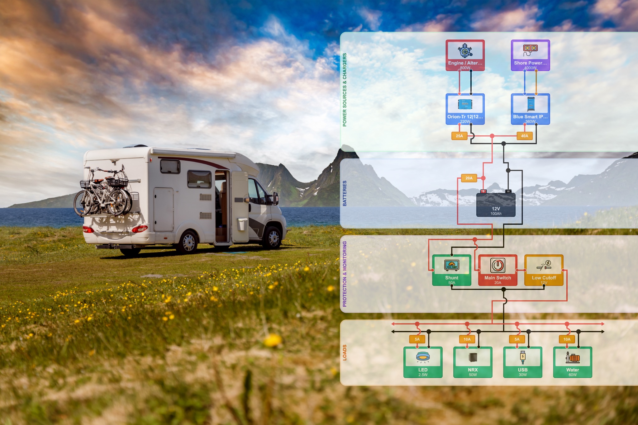
A functional layout organizes components by their role in the system, not their physical location. Power sources on the left, batteries and distribution in the center, loads on the right. Power flows left to right, like reading a sentence.
This is the layout most electrical plan apps use, and it is the best choice for planning because it makes the logical flow of power immediately obvious. You can see at a glance how solar feeds into the charge controller, which feeds the battery bus, which feeds the fuse block, which feeds each individual load.
Physical Layout
A physical layout places components roughly where they will be installed in the RV. The battery is drawn near the battery compartment, the fuse block is near the electrical panel location, and wire runs approximate real distances.
This is useful during installation -- it helps you plan routing and estimate cable lengths -- but it makes the electrical logic harder to follow. Most people create a functional schematic first, then annotate it with physical details like cable lengths and routing notes.
The Golden Rule of Layout
Power flows in one direction. Pick a direction (left to right is standard) and stick with it. Every time power reverses direction on your schematic, you create confusion. Sources on one side, loads on the other, storage and distribution in between.
Step 4: Draw the Schematic
Now it is time to actually create the diagram. Whether you are using a dedicated wiring diagram tool or pen and paper, follow this sequence.
Start with the Battery Bank
The battery is the heart of your 12V system. Place it in the center of your schematic. Everything either feeds into it or draws from it.
Draw the positive and negative terminals clearly. From the negative terminal, draw a line to your shunt (battery monitor), then to the main negative bus bar. From the positive terminal, draw a line through your main fuse and main disconnect switch to the positive bus bar.
Add Charging Sources
Working from left to right, add each charging source and its associated charger:
- Solar panels to solar charge controller to battery bus
- Shore power to AC charger / inverter-charger to battery bus
- Alternator to DC-DC charger to battery bus
Each charging path should have its own fuse or breaker on the battery side. This is where understanding fuse sizing and placement becomes critical -- every unprotected wire is a potential fire risk.
Add the Distribution Panel
From the positive bus bar, run a main feed to your fuse block or distribution panel. Each circuit gets its own fuse and its own line to the load. Label every circuit with:
- The device it powers
- The fuse rating
- The wire gauge
Add Loads
Draw each load at the end of its circuit. Group related loads together -- all lighting circuits in one area, all kitchen circuits in another. This keeps the schematic organized and mirrors how your fuse block will be laid out.
Complete the Ground Return
Every load needs a return path. Draw the ground wire from each load back to the negative bus bar. In an RV, you have two grounding strategies to consider:
- Star grounding -- Every ground runs directly back to the negative bus bar. Cleaner, less prone to ground loops, recommended for new builds.
- Daisy-chain grounding -- Grounds connect to a nearby common point, which eventually routes to the bus bar. Simpler wiring but can cause voltage drop issues.
Make your ground connections explicit on the schematic. A missing or unclear ground path is the number one cause of mysterious electrical problems.
Add Wire Details
Once the logical connections are complete, annotate each wire run with the gauge and, if known, the approximate length. If you are not sure how to select the right gauge for each run, the wire gauge sizing guide covers the calculations in detail. Do not skip this step -- an otherwise perfect schematic with missing wire specs is incomplete.
Step 5: Review and Validate
A finished schematic is not done until it has been reviewed. Here is a checklist to walk through before you call it complete.
The Protection Check
Trace every wire from source to load. At each point, ask: if this wire shorts to ground, what stops the fire? Every positive wire must have a fuse or breaker rated for the wire gauge, not just for the load. If you find an unprotected segment, add a fuse.
The Voltage Drop Check
For each circuit, calculate the voltage drop based on wire gauge, length, and current. At 12V, you have very little margin. A 3% drop is the standard maximum for most circuits, and 1% for sensitive electronics. Runs that are too long or too thin will cause dim lights, slow pumps, and unreliable operation.
The Logic Check
Follow the power path for each load:
- Can the load be turned off?
- Can the charging source be isolated?
- Is there a path for power to feed back where it should not?
- What happens if two charging sources are active simultaneously?
The Completeness Check
Compare your schematic against your original requirements list. Is every load accounted for? Every source? Did you remember the propane detector that runs 24/7? The USB outlets in the bedroom? The antenna booster?
Common Mistakes to Avoid
After reviewing hundreds of DIY schematics, certain mistakes come up again and again.
Missing fuses on charging inputs. People fuse their loads carefully but forget that the wire from the solar charge controller to the battery also needs protection. Every wire connected to a battery is a potential fault path.
Undersized main bus connections. The wire from your battery to the bus bar carries the combined current of every load and charger on the system. This is almost always the thickest wire in the system and needs an appropriately large fuse.
No main disconnect. A master switch between the battery and the rest of the system is not optional. It is how you safely shut everything down for maintenance, storage, or emergencies.
Vague grounding. Drawing a ground symbol and assuming it connects somewhere is not sufficient. Show exactly where each ground wire terminates. In an RV, grounds should ultimately return to the battery negative terminal, not just to the chassis.
Trying to show everything on one diagram. Complex systems benefit from a high-level overview schematic plus detailed sub-schematics for each subsystem (solar, AC, lighting, etc.). Cramming everything into a single drawing produces an unreadable mess.
Not updating the schematic after changes. Your schematic is a living document. If you change something during installation, update the diagram. An outdated schematic is almost worse than no schematic because it gives you false confidence.
From Schematic to Installation
A completed RV wiring schematic is your roadmap. With it in hand, you can order components with confidence, cut wire to the right lengths, and install everything methodically. Keep the schematic accessible -- laminated in your electrical compartment, saved to your phone, or stored in a shared folder.
If drawing from scratch feels like a lot of work, it is because it is. But every hour spent on the schematic saves multiple hours during installation and potentially prevents dangerous mistakes. For a deeper look at the overall process of planning your system from power consumption through to final diagram, the RV electrical system design guide covers the broader picture.
And if you want a tool that handles the symbol library, layout, fuse validation, and wire sizing for you, VoltPlan is built specifically for this. Drop in your components, connect them, and get a clean, professional 12V wiring diagram without fighting a generic drawing tool. But whether you use VoltPlan, a whiteboard, or the back of a napkin -- the important thing is that the schematic exists before the first wire is crimped.
Ready to Design Your Electrical System?
Use VoltPlan's free electrical system designer to turn these concepts into reality.
Start Your Project