Series vs Parallel Solar Panels for Campers: Wire Size, Losses, Cost
Compare series vs parallel solar panels for camper, RV, and boat systems. See the effect on wire size, power loss, MPPT input voltage, and total cable cost with real examples.
Series wiring is better than parallel for 99% of camper, RV, and boat solar installations. It produces higher voltage and lower current, which means 75% less power loss, 10x thinner cables, and lower total cost.
The numbers: A 400W solar array wired in series at 48V pulls just 8.3A and needs only 12 AWG wire. The same 400W in parallel at 12V pulls 33A and requires 4 AWG wire -- that alone is hundreds of dollars more in copper. Series is also safer because lower current means less fire risk.
Series vs Parallel: What Actually Happens Electrically
Before we get into the practical side, it helps to understand the basic physics. You don't need a degree in electrical engineering - just two simple rules, both courtesy of Gustav Kirchhoff.
Series wiring connects the positive terminal of one panel to the negative terminal of the next, forming a chain. In this configuration, the voltages of each panel add up, while the current stays the same as a single panel. Four 12V panels rated at 8.3A each wired in series give you 48V at 8.3A.
Parallel wiring connects all positive terminals together and all negative terminals together. Here, the voltage stays the same as a single panel, but the currents add up. Those same four panels in parallel give you 12V at 33.2A.
The total power (voltage times current) is identical either way - 400W. But the path that power takes through your wires is radically different, and that difference matters enormously for real-world installations.
Why? Because power loss in a wire is proportional to the square of the current (P = I² x R). Double the current and you quadruple the losses. That relationship is why series wiring wins so decisively for anything beyond a trivially short cable run. For a deeper dive into series vs parallel configurations with full diagrams, check out our series vs parallel wiring guide.
Series Wiring: The Professional Standard
Here's what actually happens in the real world:
Series wiring creates higher voltage, lower current systems. That means smaller wire gauges, fewer connection points, and dramatically reduced power losses over distance. A 400W panel array wired in series at 48V pulls just 8.3 amps versus 33 amps in parallel at 12V.
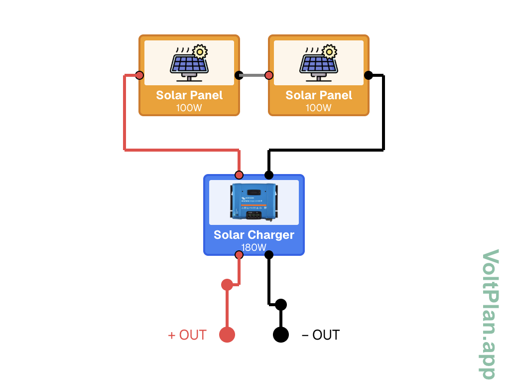
Solar panels wired in serial in VoltPlan.app
The math is brutal for parallel: Those high-current parallel systems require massive wire gauges and lose significant power to resistance. We're talking about 4 AWG (25 mm²) wire versus 12 AWG (4 mm²) for the same power - that's a huge difference in copper costs alone.
More importantly, series systems are inherently safer. Lower current means less fire risk, and MPPT charge controllers are designed to handle the higher voltages efficiently. Every professional solar installer defaults to series for good reason.
Wire Sizing: Series vs Parallel Compared
The wire gauge you need is dictated by the current flowing through it. Since series wiring carries far less current, the wire requirements are dramatically smaller. Here is a comparison assuming a 10-meter cable run (pretty typical for a rooftop-to-controller installation) with less than 3% voltage drop - the industry-accepted maximum for solar circuits.
| System Power | Config | Voltage | Current | Min AWG | Min mm² | Approx. Cost per 10m |
|---|---|---|---|---|---|---|
| 200W | Series | 24V | 8.3A | 14 AWG | 2.5 mm² | ~$8 |
| 200W | Parallel | 12V | 16.7A | 8 AWG | 10 mm² | ~$35 |
| 400W | Series | 48V | 8.3A | 14 AWG | 2.5 mm² | ~$8 |
| 400W | Parallel | 12V | 33.3A | 4 AWG | 25 mm² | ~$90 |
| 600W | Series | 72V | 8.3A | 14 AWG | 2.5 mm² | ~$8 |
| 600W | Parallel | 12V | 50A | 1 AWG | 50 mm² | ~$180 |
| 800W | Series | 96V | 8.3A | 14 AWG | 2.5 mm² | ~$8 |
| 800W | Parallel | 12V | 66.7A | 2/0 AWG | 70 mm² | ~$280 |
Notice something? The series column barely changes as you scale up. Whether you're running 200W or 800W in series, the current is the same 8.3A because you're just stacking voltage. The parallel column, on the other hand, gets progressively absurd. At 800W parallel, you need welding cable. For a complete guide to choosing the right wire gauge, see our wire gauge sizing article or run the numbers in the wire gauge calculator.
Power Loss Calculations: Real Numbers
Let's put actual numbers on this. We will use a realistic scenario: a 10-meter cable run (total conductor length of 20m accounting for positive and negative wires) from rooftop-mounted panels to a charge controller inside the vehicle.
The resistance of copper wire is approximately 0.0175 ohm per meter per mm² of cross-section. Power loss is calculated as P_loss = I² x R.
400W system, 10m cable run with 4 mm² (12 AWG) wire:
- Series (48V, 8.3A): R = 0.0175 x 20 / 4 = 0.0875 ohms. Loss = 8.3² x 0.0875 = 6.0W (1.5% loss)
- Parallel (12V, 33.3A): R = 0.0175 x 20 / 4 = 0.0875 ohms. Loss = 33.3² x 0.0875 = 97W (24.3% loss)
Read that again. With the same wire, parallel loses nearly a quarter of your power to heat while series loses just 1.5%. To bring the parallel system down to acceptable losses, you would need to upsize to 25 mm² (4 AWG) wire - which costs roughly ten times as much per meter.
800W system, 10m cable run:
- Series (96V, 8.3A) with 4 mm² wire: Loss = 6.0W (0.75% loss)
- Parallel (12V, 66.7A) with 70 mm² wire: Loss = 66.7² x (0.0175 x 20 / 70) = 22.2W (2.8% loss)
Even with cable that costs 35 times more per meter, the parallel system still loses more power than the series setup running on thin, cheap wire. The physics simply does not favor parallel wiring for anything beyond very short distances.
How MPPT Charge Controllers Handle Series Voltage
A common concern with series wiring is: "My battery bank is 12V - won't 48V or 96V from the panels damage it?" No, and here is why.
An MPPT (Maximum Power Point Tracking) charge controller is essentially a DC-DC converter. It takes the high-voltage, low-current input from your series string and converts it to the lower voltage, higher current your battery needs. This conversion is highly efficient - typically 95% to 98%.
Think of it like a transformer for DC power. The controller continuously adjusts its operating point to extract the maximum available power from the panels at any given moment (that is the "maximum power point tracking" part). Higher input voltage actually gives the MPPT algorithm more room to work with, resulting in better conversion efficiency than a low-voltage parallel input.
Most MPPT controllers designed for mobile and off-grid use accept input voltages up to 100V or 150V. A four-panel series string at nominal 48V (open-circuit voltage around 88V for typical panels) fits comfortably within those limits. Just make sure you check the Voc (open-circuit voltage) of your specific panels - this is the voltage with no load connected, and it is always higher than the nominal voltage.
Safety: The Arc Flash and Voltage Question
There is a legitimate safety concern with series wiring that deserves honest discussion: higher voltage increases the risk of arc flash. An arc flash is a sustained electrical discharge through air, and it gets easier to sustain as voltage increases. At 12V (parallel), arcing is essentially impossible. At 48V, it is unlikely but not impossible. At 96V or above, it becomes a real consideration.
However, context matters. The threshold for sustained DC arcing is generally around 40-50V, but the conditions required (damaged insulation, loose connections, contamination) are the same conditions that cause fires in high-current parallel systems. And here is the key difference: a high-current arc at 12V can dump enormous energy into a fault point, melting connectors and starting fires. A lower-current arc at higher voltage, while potentially sustained, delivers far less energy per unit time.
Practical voltage limits to be aware of:
- Most mobile MPPT controllers: 100V or 150V maximum input
- Extra-low voltage (ELV) safety threshold: 60V DC in most jurisdictions
- Typical 4-panel series string Voc: 80-92V (depending on panel specs)
- NEC rapid shutdown requirements for rooftop solar: apply above 80V in many cases
For a typical camper or boat build with 2 to 4 panels in series, you are well within safe and practical limits. If you are considering 5 or more high-voltage panels in series, check your controller's maximum input voltage rating carefully and consider the installation environment. For more on protecting your system, our fuse sizing guide covers the fundamentals of circuit protection.
Real-World Example: 4x100W Panel Setup
Let's walk through a concrete comparison. You have four 100W monocrystalline panels, each rated at 12V nominal (18V Vmp, 5.56A Imp, 22V Voc). You need a 10-meter cable run from the roof to your charge controller inside the vehicle, and you're charging a 12V battery bank.
Series configuration (4 panels in series):
- System voltage: 72V (Vmp), 88V (Voc)
- System current: 5.56A
- Wire needed: 14 AWG / 2.5 mm² (more than adequate)
- Wire cost for 10m run: roughly $8
- Power loss in wire: 5.56² x (0.0175 x 20 / 2.5) = 4.3W (1.1%)
- Power delivered to controller: 395.7W
- MPPT controller requirement: any 100V+ input, 12V output MPPT controller
Parallel configuration (4 panels in parallel):
- System voltage: 18V (Vmp), 22V (Voc)
- System current: 22.2A
- Wire needed: 6 AWG / 16 mm² (for less than 3% drop)
- Wire cost for 10m run: roughly $55
- Power loss in wire: 22.2² x (0.0175 x 20 / 16) = 10.8W (2.7%)
- Power delivered to controller: 389.2W
- Additional hardware: 4-to-1 parallel combiner box, four branch fuses
The series setup delivers more power, costs less in wire, requires no combiner box, and needs fewer fuses. It is simpler to install, easier to troubleshoot (one string, one path), and loses less energy. The only additional consideration is verifying your charge controller can handle the higher input voltage.
This is exactly the kind of calculation VoltPlan runs for you automatically. When you design your system, the wire gauges, voltage drops, and component requirements are all computed based on your actual panel specifications and cable lengths.
When Parallel Actually Makes Sense
We are not saying parallel is never the right choice. There are specific scenarios where it genuinely performs better:
Partial shading is the big one. In a series string, if one panel is shaded, it becomes a bottleneck for the entire string. The current through a series circuit is limited by the weakest link. A shadow across one panel can cut the output of all four panels dramatically. In parallel, only the shaded panel's output drops - the others continue producing at full capacity.
If your panels are mounted in locations where partial shading is unavoidable - under trees, near masts on a boat, or on a roof with dormers - parallel wiring or a combination of shorter series strings may be the better approach.
Mismatched panels are another valid reason. If you are mixing panels of different wattages, voltages, or ages, series wiring forces the current to the lowest common denominator. Parallel wiring lets each panel operate at its own voltage and current, which is less efficient in theory but more forgiving with mismatched hardware.
Very short cable runs (under 2 meters) reduce the wire sizing advantage of series wiring to the point where it barely matters. If your charge controller is mounted directly below the panels with minimal cable, the cost difference in wire is negligible.
Low panel counts with PWM controllers. If you have a single panel or two panels and a simple PWM charge controller (not MPPT), parallel at panel voltage close to battery voltage is the only option that makes sense, since PWM controllers cannot step down voltage efficiently.
Why We Focus on What Works
Could we add parallel wiring diagrams? Sure. But here's the thing: we'd rather do one thing extremely well than ten things poorly.
Series wiring covers the vast majority of real-world installations - from small RV systems to large off-grid homes. By focusing on the configuration that actually works best, we can provide better wire sizing calculations, more accurate voltage drop analysis, and clearer diagrams that won't steer you wrong.
Parallel Support: Coming When It Makes Sense
We're not anti-parallel forever. There are specific scenarios where parallel wiring makes sense - usually involving shading issues or mixing different panel types. When we add parallel support, it'll include proper current calculations, bypass diode considerations, and safety warnings about the increased fire risk.
But right now? Series wiring will solve your solar design challenges better, cheaper, and safer than parallel. That's why we start there.
Need parallel wiring for a specific application? Contact us - we're always listening to real-world requirements from actual builders.
Ready to Design Your Electrical System?
Use VoltPlan's free electrical system designer to turn these concepts into reality.
Start Your Project