


How to Install a Battery Monitor Shunt: SmartShunt, BMV-712 and Renogy Wiring Guide
Where a battery shunt goes, what connects to which side, the fused sense wire, and the LiFePO4 settings that keep SmartShunt and BMV readings accurate.
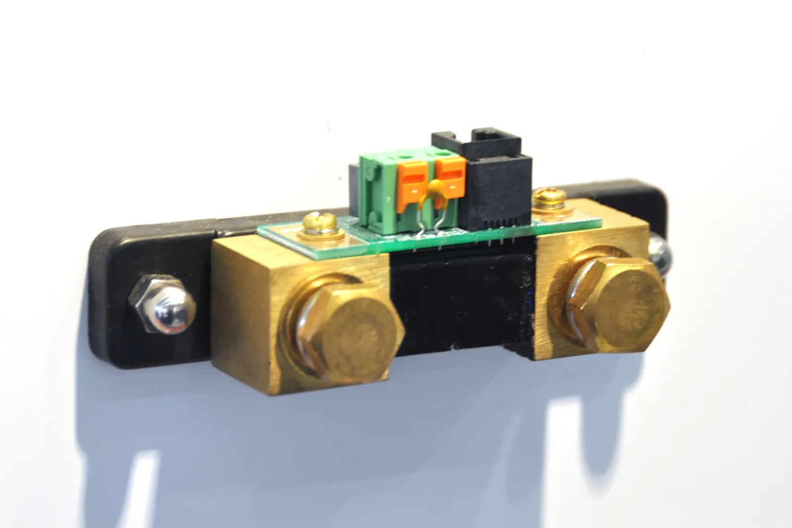
A battery monitor shunt is the only reliable fuel gauge for a camper, van or boat battery. Voltage does not do the job: a LiFePO4 battery holds an almost flat voltage between roughly 20 % and 80 % state of charge, so a voltmeter tells you little until the battery is nearly empty. A shunt measures every amp that flows in and out and counts the amp-hours, like a fuel flow meter.
Installing one takes an hour. Getting it wrong takes one cable: anything connected on the wrong side of the shunt is invisible to the monitor, and the percentage on your phone slowly drifts away from reality. This guide shows where the shunt goes, what connects to which side, and which settings make the reading trustworthy on a lithium battery. It is a researched guide, not a hands-on test. All product figures come from the manufacturers' manuals and data sheets, listed under the comparison table.
The short version
- The shunt sits in the negative cable, directly at the battery. Nothing else connects to the battery negative post.
- Everything else connects to the other side of the shunt: loads, inverter, every charger, the chassis connection.
- A thin fused sense wire runs from battery positive to the shunt. Victron includes it with a 1 A slow-blow fuse.
- The shunt carries the full system current, so its cables need the same cross-section as your main battery cables.
- Set the battery capacity, charged voltage and tail current, then let the monitor synchronise at the next full charge.
How a shunt measures
A shunt is a precise, very low resistance. A 500 A / 50 mV shunt drops exactly 50 millivolts when 500 A flow through it, which works out to 0.1 milliohm; Victron's Wiring Unlimited book lists the same 0.10 mΩ for a 500 A shunt. Those 50 mV at full rated current are the signal the monitor reads, and at everyday currents the loss is negligible. The monitor converts that tiny voltage to current and adds up amp-hours over time to calculate the state of charge.
The consequence is simple: a shunt only sees current that flows through it. A charger or load wired straight to the battery negative bypasses it, and the monitor never knows.
Three shunt battery monitors compared
All three use a 500 A shunt with M10 bolts. They differ in display, power draw and how they connect to your phone.
| Victron SmartShunt 500A | Victron BMV-712 Smart | Renogy 500A Battery Monitor (RBM500) | |
|---|---|---|---|
| Shunt | 500 A / 50 mV (also 300, 1000 and 2000 A) | 500 A / 50 mV, can be set up for other shunts up to 9999 A | 500 A (mV rating not published) |
| Operating voltage | 6.5-70 V DC | 6.5-70 V DC | 10-120 V |
| Own current draw | under 1 mA | under 1 mA (backlight off) | 10-15 mA working, 1-2 mA standby, 100 mA with backlight on (above 50 A) |
| Display | none, app via Bluetooth | round display (63 mm) plus Bluetooth | LCD display |
| Current accuracy | ±0.4 % | ±0.4 % | ±1.0 % |
| Sense wire to battery + | 1.5 m, 1 A slow-blow fuse included | 1.5 m, 1 A slow-blow fuse included | 1 m (fuse not specified) |
| Second input | starter battery, midpoint or temperature sensor | starter battery, midpoint or temperature sensor, plus programmable relay | not specified |
| Operating temperature | -40 to +50 °C | -40 to +50 °C | -10 to +60 °C |
| Protection | IP21 (IP65 versions offered) | shunt IP21, display IP55 | not published |
Sources: Victron SmartShunt manual (chapters 2, 3, 4 and 11) and data sheet, Victron BMV-712 Smart manual (chapters 3 and 11) and data sheet, Victron Wiring Unlimited (sections 2.7 and 4.8), Renogy RBM500 manual (version 3.1) and product page, all checked on 3 November 2026. Victron's BMV-712 data sheet lists the fused cable as 2 m, the manual as 1.5 m.
Which one? The SmartShunt is the shunt alone, read through the VictronConnect app or a Victron GX device. The BMV-712 adds a wall display with a buzzer and a relay, useful if you want a glance without a phone or need to switch something at low state of charge. The Renogy unit has a display but draws noticeably more current, which matters when a vehicle stands for weeks. The standard SmartShunt is rated IP21, which means dry locations only; for a damp bilge or an outside battery box, use one of Victron's IP65 versions.
Where the shunt goes
The wiring rule is the same for every brand, only the labels differ:
| Side of the shunt | Victron SmartShunt | Victron BMV-712 | Renogy RBM500 | What connects |
|---|---|---|---|---|
| Battery side | BATTERY MINUS | BATTERY ONLY | B- | the battery negative, nothing else |
| System side | SYSTEM MINUS (LOAD MINUS on units made before 2020) | LOAD AND CHARGER | P- (loads) and C- (chargers) | the negative busbar: every load, inverter and charger |
We also put the chassis connection on the system side. The manufacturers' wiring sections only list loads and chargers, but anything on the battery post bypasses the measurement, and our grounding and bonding guide explains why the shunt does not interfere with bonding.
The positive side does not change: a main fuse close to the battery positive, as our fuse sizing and placement guide explains. Only the thin sense wire is new. It powers the monitor and lets it measure battery voltage.
Installation step by step
- Check the shunt rating. Victron's rule: the shunt must be rated for the maximum DC current all consumers draw together. A 2,000 W inverter at full load already pulls about 2,000 ÷ (12 V × 0.9) ≈ 185 A from a 12 V battery, so a 500 A shunt covers most camper and boat systems. Above that, use a 1000 A or 2000 A shunt.
- Switch everything off and disconnect the battery negative. Renogy's manual asks you to disconnect the battery negative before installation; switching all loads and chargers off first is good practice for any brand. With the negative off, a slipping spanner on the positive side cannot cause a short.
- Mount the shunt close to the battery in a dry place (unless you use an IP65 version). The SmartShunt and the BMV shunt have two 5.5 mm mounting holes; screws are not included.
- Battery negative to the battery side. Use the M10 bolt and do not exceed the torque in the manual; Victron specifies a maximum of 21 Nm for its 500 A shunt.
- System side to the negative busbar. Move every negative that used to sit on the battery post to the busbar: inverter, DC-DC charger, solar controller, mains charger, fuse box and, in our recommendation, the chassis connection. On SmartShunts made before 2020 this side is labelled LOAD MINUS.
- Sense wire last. Fit the red fused cable to the Vbatt+ (SmartShunt) or +B1 (BMV) terminal, then its lug onto battery positive. This is the order in Victron's manual. On the Renogy, the manual specifies 0.3-0.75 mm² wire for the B+ connection; like any wire leaving battery positive, give it a small fuse close to the battery.
- Optional second input. Victron's Aux input measures a starter battery, the midpoint of a 24 V or 48 V bank, or battery temperature with the optional temperature sensor. For a starter battery, its negative must also be on the system side. The temperature sensor replaces both fused red cables: it connects to Aux and Vbatt+ and has its own lug for battery positive.
- Configure and test. Switch on a known load and check that the current shows as negative. If charging shows as discharge, the two negative cables are swapped. On the Renogy monitor, a blinking backlight under load is the sign for swapped B- and P-.
The shunt carries every amp of the system, so the two short cables to the battery and the busbar need the same cross-section as your main positive cable. The wire gauge calculator gives the size for your largest current, the fuse size calculator the matching main fuse.
LiFePO4 settings that make the percentage trustworthy
The factory settings of Victron's monitors are tailored to lead-acid batteries. For a lithium battery, the SmartShunt and BMV manuals recommend changing these values:
| Setting | Factory default (12 V) | Victron's recommendation for lithium |
|---|---|---|
| Battery capacity | 200 Ah | your battery's rated capacity |
| Charged voltage | 14.0 V | 13.9 V |
| Tail current | 4 % of capacity | if your charger stops below a set current, higher than that current |
| Charged detection time | 3 min | no lithium-specific value |
| Peukert exponent | 1.25 | 1.01, unless your battery supplier says otherwise |
| Charge efficiency factor | 95 % | 98 % |
| Discharge floor | 50 % | 10-20 %, unless your battery supplier says otherwise |
Source: Victron SmartShunt manual, sections 4.4 and 7.2, checked on 3 November 2026.
Why these matter. A shunt counts amp-hours, and small errors add up over days. The monitor corrects itself by synchronising to 100 % when three conditions hold at once: the voltage is above the charged voltage, the current is below the tail current, and both stay that way for the charged detection time. Set the charged voltage just below your charger's absorption voltage. Too low, and solar at sunset can trigger a false 100 %; too high, and the monitor never synchronises and the reading drifts. After the first installation, press "Synchronise" (the button's name in the English app) in VictronConnect once the battery is full.
On the Renogy RBM500, the main setting is the battery capacity (default 100 Ah, adjustable from 0.1 to 9999 Ah).
Common mistakes
- A cable left on the battery negative. The classic: an inverter or a diesel heater wired straight to battery minus. The monitor misses its current, and the state of charge reads too high every evening. Our diesel heater wiring guide shows the heater negative on the system side.
- Chassis on the battery post. The chassis connection belongs on the system side, too, otherwise any current through it bypasses the measurement.
- Shunt in the positive cable. All three monitors here measure in the negative. Renogy's manual states this explicitly.
- Capacity or charged voltage never set. With the lead-acid defaults on a lithium battery, the monitor rarely synchronises and the percentage wanders.
- Long storage with the monitor connected. A monitor keeps drawing current. Victron's manual warns that this residual current can destroy a lithium battery if the system is left unattended long enough to discharge the battery completely, and recommends interrupting the positive supply in that case; its warning quotes a draw of under 12 mA, more than the under 1 mA in the technical data. Our LiFePO4 winter guide covers the rest of winter storage.
- Self-heating batteries. A battery with built-in heating pads warms itself from the charge current behind the shunt, so the shunt counts heating energy as charge. Our self-heating LiFePO4 comparison explains the effect.
Plan the shunt into your diagram
The easiest way to get the wiring right the first time is to draw it before you buy. In the free VoltPlan diagram editor, add battery, chargers, inverter and loads; VoltPlan adds a battery monitor shunt rated at 1.5 times your total load current (rounded up to the next 50 A), a main switch and a low-voltage disconnect, and sizes cables and fuses for every circuit. Once the shunt is in and has a week of data, feed the real daily amp-hours into the battery runtime calculator and see how many days your battery really lasts.
FAQ
Does a battery shunt go on the positive or the negative side?
On the negative side. The shunt sits in the negative cable directly at the battery: the battery negative connects to one side, everything else to the other. Only the thin sense wire goes to battery positive.
Can I connect anything else to the battery negative terminal?
No. Anything on the battery negative post bypasses the shunt, and the monitor does not count its current. Move every negative to the busbar on the system side of the shunt, including the chassis connection.
What size shunt do I need?
One rated for the maximum current of all loads together. A 2,000 W inverter at 12 V draws about 185 A at full load (2,000 W ÷ 12 V at about 90 % inverter efficiency), so a 500 A shunt covers most camper and boat systems. Victron also offers 1000 A and 2000 A versions of the SmartShunt.
Does the sense wire need a fuse?
Yes. Victron supplies the SmartShunt and the BMV-712 with red cables that have a 1 A slow-blow fuse built in. If your monitor comes without one, fit a small fuse close to the battery positive, as for any wire leaving the battery.
Why does my SmartShunt never show 100 %, or show 100 % too early?
The synchronisation settings do not match your charger. The monitor sets 100 % only when the voltage is above the charged voltage and the current below the tail current for the detection time. Set the charged voltage just below the charger's absorption voltage (Victron suggests 13.9 V for 12 V lithium). If your charger stops charging below a set current, set the tail current above that current.
Does a battery monitor drain the battery?
A little. Victron states under 1 mA for the SmartShunt and the BMV-712 with the backlight off. Renogy states 10-15 mA while working and 1-2 mA on standby for the RBM500. If the vehicle stands long enough for that draw to empty the battery, interrupt the monitor's positive supply.
This article was created with the assistance of AI.
Ready to Design Your Electrical System?
Use VoltPlan's free electrical system designer to turn these concepts into reality.
Start Your Project